
Automated Vial Capping Systems: Architecture, Control, and Throughput
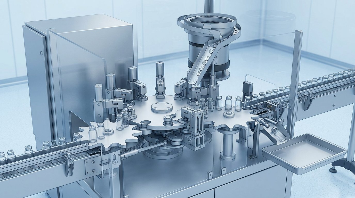
An automated vial capping system is the machine at the end of a fill-finish line that sorts and feeds aluminium seals, places one on each stoppered vial, crimps it under the vial neck flange, and rejects any unit that fails an in-process check. Machines are built on two architectures, linear (inline) and rotary turret, and their real output is governed by crimp-force control, seal-feed reliability and reject rate rather than by the nameplate speed on the datasheet.
This guide covers what the machine is made of, how the architectures differ, the crimping head designs in use, how capping force is set and verified, the sensors that decide what gets rejected, and where the capper sits relative to the aseptic core. For the mechanics of the crimp itself, see vial crimping explained.
Key takeaways
- A capping system is six subsystems working together: vial handling, seal sorting and feed, seal placement, the crimping head, in-process sensors, and the reject station.
- Inline machines index vials through one or a few heads and suit lower and mid-range speeds; rotary turret machines carry many heads around a continuously moving turret and reach the high hundreds of vials per minute.
- Three crimping head families dominate: the spinning single-roller head, the multi-roller head, and the collet or segmented-jaw head that closes in one stroke.
- Capping force is set by clamping force and head height and is increasingly servo-controlled and monitored per cycle rather than fixed by spring preload.
- Residual seal force (RSF) is the measurable output of capping: the vertical force a compressed stopper exerts on the vial land after crimping, and the industry’s nearest thing to a quantitative measure of seal tightness.
- Under EU GMP Annex 1, vials with missing or displaced stoppers are rejected before the crimping head, and stoppered vials are protected by a Grade A air supply until the cap is crimped when capping runs outside the aseptic core.
- In practice the bottleneck is usually seal feed and format changeover, not the crimping head.
What an automated capping system is made of
Every capper, whatever its architecture, is the same six subsystems arranged differently.
| Subsystem | What it does | Typical failure it causes |
|---|---|---|
| Vial infeed and handling | Receives vials from the filler or lyophiliser and presents them to the heads, via a screw feed and starwheel or a puck conveyor | Toppled or jammed vials, glass-to-glass contact |
| Seal sorting and feed | Orients seals from bulk into single file, typically a vibratory bowl or centrifugal sorter feeding a gravity or air-assisted track | Track starvation, double-feeds, misoriented seals |
| Placement | Sets one seal squarely on the stoppered vial before the head engages | Tilted or off-centre seals entering the crimp |
| Crimping head | Rolls the aluminium skirt under the vial neck flange while holding the seal down | Loose, over-crimped, or cracked crimps |
| In-process sensors | Check stopper height, seal presence, capped height, and crimp appearance | Undetected defects reaching inspection |
| Reject station | Diverts failing vials to a locked reject container with a reconciliation count | Uncounted rejects, reconciliation failures |
The head gets the attention, but the feed and handling subsystems are where most stoppages originate. A correctly set crimping head rarely fails on its own; a seal track that starves for two seconds stops the line.
Inline versus rotary architecture
The choice between inline and rotary is a choice between simplicity and speed.
| Inline (linear) capper | Rotary turret capper | |
|---|---|---|
| Motion | Vials index or travel in a straight line past one or a few fixed heads | Vials travel on a rotating turret with a head above each pocket, crimping while in motion |
| Head count | One to a few | Typically six to twenty-plus |
| Speed range | Low to mid range, suiting clinical, small batch and flexible production | High, with the top of the range specified in the high hundreds of vials per minute |
| Footprint | Compact | Larger, and usually integrated with the filler as one machine block |
| Format change | Fewer parts to swap | More change parts, and changeover time becomes a real capacity cost |
| Best fit | Multi-product sites, small volumes, development and clinical supply | Single-product or few-product commercial lines running long campaigns |
Rotary machines get their throughput from parallelism rather than from crimping faster: each head has the same dwell as an inline head, but many crimps happen at once. A rotary machine also degrades gracefully, since one misbehaving head produces a repeating defect pattern rather than stopping the line. That is why per-head traceability of rejects is worth having.
Crimping head designs
Three head designs are in common use, and they differ in how the aluminium skirt is folded.
- Spinning single-roller head. The head descends onto the seal, applies a downward clamping load, and a single roller orbits the skirt, progressively folding it under the flange. Gentle on the glass and tolerant of dimensional variation, but the crimp takes a full revolution or more of dwell.
- Multi-roller head. Two, three or four rollers engage the skirt simultaneously and close inward. Shorter dwell than a single roller and a more symmetric fold, at the cost of more tooling and a tighter setup window.
- Collet or segmented-jaw head. A ring of segments closes radially in a single stroke, forming the whole crimp at once. The fastest per-cycle option and well suited to inline machines, but the least forgiving of dimensional variation, since the geometry is fixed by the tooling rather than swept by a roller.
The choice interacts with the seal. A design with a deeper skirt or a stiffer aluminium temper generally wants a rolling action; a shallow, soft skirt crimps cleanly in a collet. This is one reason a capping recipe is qualified against a specific seal specification rather than a seal size.
Controlling the capping force
Capping force is set by two parameters, the clamping load on the seal and the head height relative to the vial, and it is most often the setting responsible for out-of-window crimps. Traditional machines fix the clamping load with a spring stack and set head height mechanically, so the force actually applied varies with vial height tolerance and wear. Current machines increasingly use servo-driven heads with load cells, making clamping force a recipe value that can be recorded per vial.
Force that is too low leaves the stopper under-compressed and the skirt loosely folded, which is a container closure integrity risk. Force that is too high can deform the stopper, distort the seal, or fracture the vial’s neck or land. Because the window is narrow, and because vial and stopper dimensions vary within their own tolerances, monitoring the force actually applied is more informative than trusting the setting.
Residual seal force: measuring what the machine actually did
Residual seal force is the vertical force a compressed rubber stopper exerts on the vial’s sealing land after the seal has been crimped, and it is the standard quantitative way to characterise a capping process. It is measured off-line on a compression tester: the capped vial is loaded and the response curve reveals the point at which the applied load overcomes the stopper’s residual compression.
RSF is used to set cappers consistently, to compare settings across sites, and to bracket a capping process during qualification. Work published in the PDA Journal of Pharmaceutical Science and Technology has examined where its variability comes from, identifying the dimensional tolerances of the packaging components as a dominant contributor rather than the capper or the tester. That is the practical argument for component consistency: the same machine setting produces different seals if the components drift. Integrity itself is still demonstrated by container closure integrity testing, not inferred from RSF.
In-process checks and reject logic
A modern capper is as much an inspection station as a forming station, and the checks run in a fixed order.
- Stopper height, before capping. A sensor measures the seated height of each stopper and rejects vials with a missing or displaced stopper. Annex 1 is explicit that this happens before capping, because a raised stopper crimped over looks acceptable from the outside and is not. The reject limit needs to be qualified against integrity data rather than set by eye.
- Seal presence and orientation at placement. Detects a starved track, a double-feed, or a seal sitting proud.
- Capped height after crimping. A height outside the window indicates an incomplete crimp, a doubled seal, or a stopper that has lifted.
- Vision inspection of the crimp. Cameras check the skirt fold, the plastic button on a flip-off seal, and cosmetic defects, with defect classes trained per seal design.
- Reject and reconciliation. Failing vials divert to a secured reject station with counters that reconcile against the batch record.
Everything the capper detects is a leading indicator. The 100% visual inspection later in the vial fill-finish process is the formal check, but a capper that rejects reliably keeps the defect population small enough that inspection is not doing the capper’s job.
Where the capper sits relative to the aseptic core
Capping can be performed inside the aseptic core with sterilised seals, or as a clean process outside it, and the environmental controls differ accordingly. Capping inside an isolator or a restricted access barrier system keeps the operation in the high-grade zone but complicates seal transfer, since the seals must be sterilised and brought in aseptically. Capping outside the core is more common and is treated as a clean process: stoppered vials are protected by a Grade A air supply from the point they leave the filling zone until the cap is crimped, so the partly closed vial is never exposed to unclassified air.
The transfer point is defined so carefully because a stoppered, uncapped vial is not a sealed package. The stopper is held only by friction, and this is the window in which a displaced stopper can admit contamination. That is why sterile vial sealing treats capping as the closing event of the aseptic process rather than an afterthought.
What actually limits throughput
On a running line, the constraints are rarely in the crimping head. In descending order of how often they bite:
- Seal feed reliability. Sorters and tracks are sensitive to seal geometry, surface finish, and static. A seal that occasionally hangs in the track costs more output than a slower head would.
- Reject rate. Effective output is the rated speed minus everything diverted, and pushing the speed up usually raises the reject rate faster than it raises output.
- Format changeover. On a multi-product site, hours spent swapping change parts and re-qualifying a recipe come straight off available capacity.
- Upstream rate matching. A capper faster than the filler simply idles. Accumulation smooths short stoppages, but the line runs at its slowest sustained stage.
Which is why buying a faster capper rarely delivers a proportional gain. Component consistency, changeover discipline, and reject rate move the number more.
How this works in practice at Autofits
Autofits supplies the consumable a capping system handles several hundred times a minute, so the seal is manufactured with the machine in mind. The range covers FlipTop aluminium-plastic seals in bridge, button and flower sub-types, tear-off and tear-down aluminium seals, and aluminium pilfer-proof (ROPP) caps across the product range. Seals are produced to tight dimensional tolerances and screened by high-speed visual inspection, because dimensional variation is what turns a qualified capping recipe into a rising reject rate. Production runs in a 75,000 sq ft Nashik facility with an ISO Class 8 cleanroom, under an ISO 15378:2017 quality system alongside ISO 9001:2015 and ISO 14001:2015 certification and a Drug Master File. The full certification set is on the quality page.
Frequently asked questions
What is an automated vial capping system?
It is the machine at the end of a pharmaceutical fill-finish line that sorts aluminium seals from bulk, places one on each stoppered vial, crimps the skirt under the vial neck flange, and rejects any vial failing an in-process check. It combines vial handling, seal feeding, a crimping head, sensors and a reject station, and usually sits immediately downstream of the filling machine.
What is the difference between an inline and a rotary vial capper?
An inline capper indexes vials in a straight line past one or a few crimping heads and suits lower volumes and multi-product sites. A rotary capper carries many heads on a continuously turning turret, crimping several vials at once, and reaches the high hundreds of vials per minute. Rotary machines gain speed from parallelism rather than from faster crimping, at the cost of more change parts.
How is capping force controlled?
By the clamping load applied to the top of the seal and the head height relative to the vial. Older machines fix these mechanically with spring stacks, so the applied force varies with component tolerance and wear. Current machines use servo-driven heads with load cells, so clamping force becomes a recorded recipe value that can be monitored cycle by cycle.
What is residual seal force?
Residual seal force (RSF) is the vertical force a compressed rubber stopper exerts on the vial’s sealing land after the aluminium seal has been crimped. Measured off-line on a compression tester, it is the standard quantitative way to characterise a capping process and to bracket capping during qualification. Container closure integrity is still demonstrated by a separate leak test.
What checks does a capping machine perform?
Stopper height before capping (to reject vials with a missing or displaced stopper), seal presence and orientation at placement, capped height after crimping, and vision inspection of the finished crimp and the plastic button. Failing vials divert to a secured reject station with counts that reconcile against the batch record.
Does capping have to happen inside the aseptic core?
No. Capping can be done inside an isolator or restricted access barrier system with sterilised seals, or as a clean process outside the core. Where it is done outside, EU GMP Annex 1 expects stoppered vials to be protected by a Grade A air supply until the cap has been crimped, because a stoppered but uncapped vial is not yet a sealed package.
Related reading
- Vial sealing machine types: manual, semi-automatic and automatic
- Vial crimping explained
- The vial fill-finish process, end to end
- Sterile vial sealing
- EU GMP Annex 1 and container closure integrity
- Container closure integrity testing
Sources
- European Commission: EudraLex Volume 4, EU GMP Annex 1, Manufacture of Sterile Medicinal Products (2022) (https://health.ec.europa.eu/medicinal-products/eudralex/eudralex-volume-4_en)
- PDA Journal of Pharmaceutical Science and Technology: Quantifying the Vial Capping Process, Residual Seal Force and Container Closure Integrity (https://journal.pda.org/content/73/1/2)
- USP-NF: General Chapter <1207>, Package Integrity Evaluation, Sterile Products (https://www.usp.org/)
- FDA: Guidance for Industry, Sterile Drug Products Produced by Aseptic Processing, Current Good Manufacturing Practice, September 2004 (https://www.fda.gov/regulatory-information/search-fda-guidance-documents/sterile-drug-products-produced-aseptic-processing-current-good-manufacturing-practice)
*Last updated: 2026-07-31. This article is general technical information, not engineering or compliance advice; qualify capping equipment and settings against your own components and process.*
